< | Help Index | >

|
Automation
|
Automating The Mistral
In some cases it may be desirable to control the Mistral using something besides the
keyboard or mouse. You may also have another system that needs to know when the Mistral
is looking for a switch to be pressed or whether a keypad tested good or bad. In these
situations the Mistral software can communicate with external hardware or another test
system using a digital input/output card installed in the computer or an external USB module.
Selecting And Installing A Digital I/O Card
The Mistral supports products manufactured by
Measurement
Computing
. We are currently recommending the following internal cards and external USB modules, although any Measurement
Computing device with digital inputs and/or outputs should work. You will need to select a
product that interfaces with the equipment you plan to use.
External USB Module
|
|
USB-DIO24
|
|
8 TTL outputs, 8 TTL inputs
|
Internal PCI Bus Card
|
|
PCI-PDISO8
|
|
8 relay outputs, 8 isolated inputs
|
Internal ISA Bus Card
|
|
CIO-PDIS08
|
|
8 relay outputs, 8 isolated inputs
|
|
CIO-RELAY08
|
|
8 relay outputs
|
|
CIO-DIO24
|
|
8 TTL outputs, 8 TTL inputs
|
Install the card or module following the instructions provided Measurement Computing. You will need to run
the Instacal software included with the device to install the "board" before it will be recognized by the Mistral software.
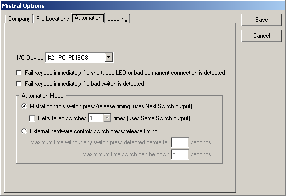
Setting Up Automation
Before using automation, the Mistral needs to know which I/O device you are using and how
the external hardware will work. Select "Mistral Options..." from the "File" menu to open
the Mistral Options window and choose the Automation tab. Note the "Mistral Options..." menu item will not be
available if there is an edit mode password and it was not entered when the program was
launched or you are in the middle of testing keypads.
|
- I/O Device
-
Select the card or USB module installed or "(None)" to disable automation. If your device does not appear in
the list or the list is disabled, make sure the it is installed correctly and has been added to the
system by running the Instacal program provided by Measurement Computing. You may need to restart your computer
after installing the Instacal program before the device will be recognized by the Mistral software. For USB modules
you must connect the module to the computer before running the Mistral software.
- Fail Keypad immediately if a short, bad LED or bad permanent connection is detected
-
If this is checked testing of the Keypad will end immediately when the failure is found. Testing of
switches will be skipped.
- Fail Keypad immediately if a bad switch is detected
-
If this is checked testing of the Keypad will end immediately as soon as a bad switch is detected. If the
Mistral is controlling switch press timing and Retry is enabled, the Mistral will retest the switch the requested number
of time before the switch is considered "bad".
- Automation Mode
-
This section allows you to select two modes of controlling switch presses.
- Mistral controls switch press/release timing (uses Next Switch output)
-
This is the fastest mode of automated
testing since the Mistral will make the Next Switch Down output inactive as soon
as it has measured the switch resistance.
If this option is selected, the external hardware will need to sequence
through the switches on the Keypad in response to the Next Switch Down output. Each
time Next Switch Down goes active the next switch on the Keypad should be pressed,
until all switches have been pressed. Each should be held down until the
Next Switch signal goes inactive.
- Retry failed switches X times (uses Same Switch output)
-
If this is checked, the Mistral will assert Same Switch Down if
the last switch pressed when Next Switch Down was active was found to be
bad. The external hardware will re-press the same switch just pressed
(instead of advancing to the next switch) until Same Switch Down goes
inactive. The number of times to Retry can be set by choosing from the
list.
- External hardware controls switch press/release timing
-
If this option is selected, the external hardware should sequentially press
all of the switches on the Keypad when "Scanning for switches" output goes active.
It will be up to the external hardware to hold each switch down until the Mistral
detects it and to allow enough time between switch presses.
- Maximum time without switch press detected before fail
-
If no switch press is detected for the time indicated, the testing of the Keypad
stops. The Keypad will have failed since the Mistral was still looking for a switch
press. This feature ends the test if a switch is not detected when pressed.
- Maximum time switch can be down
-
If a switch is pressed continuously for the time indicated the testing of the Keypad
stops and the part is failed. This will end the test for stuck switches.
|
In addition to setting up the automation features in the Mistral Options window, you
will need to enable automation in each Keypad File. See
Edit
Info
window for information on enabling automation for a Keypad File.
Output Signals
Output signals are on the first port of devices with multiple I/O ports (usually Port A).
For relay output devices the common (C) pin is connected to the normally open (N.O.) pin
when the output is "active". For devices with TTL outputs, the output is high when
active.
|
- 0 - Keypad Passed
Active when test is complete and Keypad was good.
- 1 - Keypad Failed
-
Active as soon as Mistral sees something wrong with a Keypad. Goes inactive if
the error condition goes away during the test.
- 2 - Test Complete
-
Test is done and Mistral is ready for the next Keypad. Keypad Passed and Keypad Failed
indicate the result of the test.
- 3 - Scanning for shorts, LEDs and permanent connections
Active when doing initial Keypad test.
- 4 - Scanning for switches
Active when waiting for switch presses.
- 5 - Next Switch Down
-
If the Mistral is selected to control switch timing in
Mistral Options, hardware should press the next switch on the
Keypad when this is active. The switch should be held down until Next Switch Down goes
inactive.
- 6 - Same Switch Down
-
If enabled in Mistral Options, hardware should press the
same switch that was just pressed when this is active. The switch should be held down
until Same Switch Down goes inactive. This is activated if a switch is bad or not
detected after Next Switch Down. The number of times this happens each time a switch
fails is set in Mistral Options.
- 7 - Not Used
|
Input Signals
For devices with multiple I/O ports, inputs will be on the second port (usually Port B).
On I/O devices with TTL level inputs, inputs are active high (5VDC) and all unused inputs must
be tied to ground. For devices with isolated inputs, an input is active when voltage is
applied and unused inputs can be left unconnected. All inputs that duplicate program
buttons do not work unless the corresponding button is enabled.
|
-
0 - Test First Keypad/Test Next Keypad (Production Testing) or Test Life
Cycle Keypad (Life Cycle Testing)
Functions the same as clicking on the button on the screen.
- 1 - Retry Test
Functions the same as clicking on the button on the screen.
- 2 - Pass
Functions the same as clicking on the button on the screen.
- 3 - Fail
Functions the same as clicking on the button on the screen.
-
4 - End Job (Production Testing) or End Life
Cycle Test (Life Cycle Testing)
Functions the same as clicking on the button on the screen.
- 5 - Enter
Functions just like pressing the Enter key or space bar on the keyboard.
- 6 - End Test
-
If the Mistral is in the process of testing a keypad, activating this input causes the test to
be stopped. Test Complete will be asserted and Pass or Fail indicated.
- 7 - Not Used
|
Automatic Test Termination
When switch timing is being controlled by external hardware,
testing of a Keypad can end automatically for several reasons.
- All switches were cycled (pressed and released) at least once. The Keypad could have passed or failed.
- No switch press detected for 8 seconds (adjustable in Mistral Options). Keypad failed.
- Switch pressed continuously for 5 seconds (adjustable in Mistral Options). Keypad failed.
- A short was found between items. Keypad failed.
- An LED found was that is not in the Keypad File. Keypad failed.
When the Mistral is controlling switch timing,
testing of a Keypad will end automatically for the following reasons.
-
All switches were cycled (pressed and released) at least once. The Keypad could have passed
or failed. If Retry is enabled in the Mistral Options window the
Mistral will make the requested number of attempts to get a good reading.
- A short was found between items. Keypad failed.
- An LED was found that is not in the Keypad File. Keypad failed.
For both modes of operation the test can also be stopped immediately if a short, LED or permanent
connection error or a bad switch is found by checking the corresponding item in the Mistral
Options.
Examples
Setting up your own automation system requires an external PLC or other controller that
will monitor and respond to signals from the I/O device. Several examples may help illustrate
how this communication could work.
Example 1: External hardware controls switch press/release timing - The keypad
you are testing has three switches labeled S1, S2 and S3. Your test hardware's controller
is connected to three pneumatic plungers. The controller will begin pressing switches when
"Scanning for switches" goes active. It will press each switch once by activating the
corresponding plunger for a preprogrammed amount of time and then move on to the next switch
in the sequence.
Set the Automation Mode to "External hardware controls switch press/release timing" in
Mistral Options.
The timing diagram below shows the state of the output signals during the test of
one Keypad. A description of what is happening at each of the numbered times follows.
Example 1 Timing Diagram
-
The Mistral begins by scanning for shorts, LEDs and permanent connections. The output
"Scanning for shorts, LEDs and permanent connections" goes active.
-
"Scanning for switches" goes active indicating the Mistral has completed scanning for shorts, etc. and has begun
looking for switch presses.
-
The controller should recognize that "Scanning for switches" has gone active and
lower the plunger for S1, the first switch in the sequence.
After the amount of time programmed into the controller passes, S1 should be released.
"Scanning for switches" is still active so the controller should press S2.
-
The controller releases S2. The switch resistance measured by the Mistral was bad
so the Mistral asserts "Keypad Failed".
The controller lowers the plunger for S3.
-
The controller releases S3. At this point the controller must wait for "Scanning
for switches" to go inactive. It should not start the sequence over again. This is because
if a switch was defective and the Mistral did not detect it when pressed, the controller
will need to wait for the Mistral to time out before it will recognize the test is
complete.
-
The Mistral has detected that each switch has been pressed at least once so the
test is complete. It makes "Scanning for switches" inactive and "Test Complete" active.
Note that since one of the switches failed, "Keypad Failed" is still asserted. These two
signals will remain active until the "Test Next Keypad" button is pressed, either using the mouse or
keyboard or through the "Test First Keypad/Test Next Keypad" automation input.
Note that if you set up your Mistral to fail a Keypad as soon as a bad switch is detected,
the test could stop in the middle at which time "Scanning for switches" would go inactive.
Your controller should stop pressing switches and wait for "Scanning for switches" signal to go
active again. If "Switches must be pressed in sequence" is
checked in the Edit Info window your controller should
reset to the first switch each time the "Scanning for switches" signal to goes
active.
Example 2: Mistral controls switch press/release timing - The keypad you are
testing has three switches labeled S1, S2 and S3. Your test hardware's controller is
connected to three pneumatic plungers. You want to test as rapidly as possible so your
controller will monitor "Next Switch Down" and "Same Switch Down".
Set the Automation Mode in Mistral Options to "Mistral controls switch press/release
timing" and check "Retry failed switches", setting the number of Retries to 2.
The timing diagram below shows the state of the output signals during the test of
one Keypad. A description of what is happening at each of the numbered times follows.
Example 2 Timing Diagram
-
The Mistral begins by scanning for shorts, LEDs and permanent connections. The output
"Scanning for shorts, LEDs and permanent connections" goes active.
-
The Mistral has completed scanning for shorts, etc. and has begun scanning for switches ("Scanning for switches" is active) and
asserts "Next Switch Down". The controller should lower the plunger for one of the switches, say S1. Note it doesn't matter which
switch is pressed first as long as they are all pressed in sequence.
The Mistral makes "Next Switch Down" inactive. The controller should raise the plunger for S1.
-
The Mistral asserts "Next Switch Down" again. This means that the Mistral has
decided S1 is good. The controller should press S2.
The Mistral makes "Next Switch Down" inactive. The controller should raise the plunger for S2.
-
"Same Switch Down" is asserted. This means the Mistral did not get a good
value for S2. The controller should lower the plunger for S2 again.
The Mistral makes "Same Switch Down" inactive. The controller should raise the plunger for S2.
-
The Mistral asserts "Same Switch Down" again. This means the Mistral did not get a
good value for S2 the second time it was tried and it would like to try it one more time. The
controller should lower the plunger for S2 again.
The Mistral makes "Same Switch Down" inactive. The controller should raise the plunger for S2.
-
"Next Switch Down" goes active. Since "Keypad Failed" was not asserted
and this was the last time this switch would be tried the Mistral must have got a good
result for S2. The controller should press S3.
The Mistral makes "Next Switch Down" inactive. The controller should raise the plunger for S3.
-
The Mistral is done scanning for switches ("Scanning for switches" inactive) and has
completed testing the Keypad ("Test Complete" is active). Since all the switches passed,
"Keypad Passed" has been asserted.
Note that if you set up your Mistral to fail a Keypad as soon as a bad switch is
detected, the test could stop in the middle of testing. Again your controller program
doesn't need to care as long as "Switches must be pressed in sequence" is not
checked in the Edit Info window. Just make sure that if the last switch you pressed was S3 and you
see "Next Switch Down" go active, you lower the plunger on S1. If "Switches must be pressed in sequence" is
checked in the Edit Info window, your controller should
reset to the first switch each time the "Scanning for switches" signal to goes
active.
< | Help Index | >
< | Index de Ayuda | >
|
|
Automatización
|
Automatizando el Mistral
En unos casos es deseable controlar el Mistral usando algo en lugar del teclado o el mouse. Tambien puede tener otro sistema que necesita cuando el Mistral está buscando por un
interruptor para oprimir o si un teclado pasó o falló. En estas situaciones el software Mistral puede comunicar con hardware exterior u otro sistema de pruebas usando una tarjeta
I/O digital instalada en la computadora o un módulo externo de USB.
Seleccionando e Instalando una Tarjeta I/O Digital
El Mistral soporta productor producidos por Measurement Computing.
Actualmente estamos recomendando la siguientes tarjetas internas y módulos externos de USB, a pesar de que cualquier
dispositivo de Measurement Computing con I/O digital debe funcionar. Necesita seleccionar un producto que interface
con el equipo que planea en usar.
Módulo Externo USB
|
|
USB-DIO24
|
|
8 TTL outputs, 8 TTL inputs
|
Tarjeta Interna PCI
|
|
PCI-PDISO8
|
|
8 relay outputs, 8 isolated inputs
|
Tarjeta Interna ISA
|
|
CIO-PDIS08
|
|
8 relay outputs, 8 isolated inputs
|
|
CIO-RELAY08
|
|
8 relay outputs
|
|
CIO-DIO24
|
|
8 TTL outputs, 8 TTL inputs
|
Instale la tarjeta or el módulo siguiendo las instrucciones de Measurement Computing. Necesitará correr el software
Instacal incluido con el dispositivo para instalar la "tarjeta" antes de ser reconocido por el software Mistral.
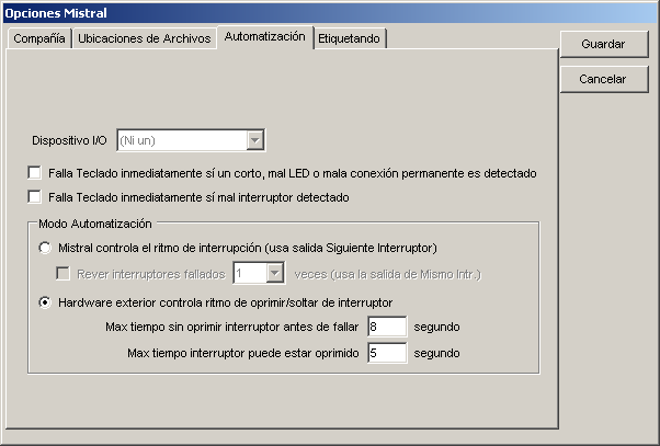
Preparando Automatización
Antes de usar automatización, el Mistral necesita saber cual dispositivo I/O está usando y como el hardware externo trabajará. Seleccione
"Mistral Opciones..." bajo el menú Archivo para abrir la ventana de opciones y escoja el tab Automatización. Nota que el menú "Mistral Opciones..."
no va ser disponible si hay una clave para editar y no se ha entrado cuando el programa comenzó o está en medio de una prueba.
|
- Dispositivo I/O
-
Seleccione la tarjeta o el módulo USB instalado o "(Ni un)" para deshabilitar automatización. Si su dispositivo no aparece en la lista o la lista
está deshabilitada, asegure que está instalado correctamente y que se ha agregado al sistema corriendo el programa Instacal de Measurement Computing.
Puede necesitar reiniciar la computadora antes que el dispositivo sea reconocido por el Mistral. Para módulos USB necesita conectar el módulo
a la computadora antes de iniciar el software Mistral.
- Falla Teclado inmediatamente si un corto, mal LED o mala conexión permanente es detectado
-
Si esta opcion es seleccionada, la prueba del Teclado termina inmediatamente cuando una falla es encontrada. No se hacen pruebas de interruptores.
- Falla Teclado inmediatamente si mal interruptor detectado
-
Si esta opcion es seleccionada, la prueba del Teclado termina inmediatamente cuando un mal interruptor es detectado. Si el Mistral controla el ritmo
de oprimir los interruptores y Rever es habilitado, el Mistral vuelve a probar el interruptor el número de veces pedido antes de considerar el interruptor
"malo".
- Modo Automatización
-
Esta sección le permite seleccionar dos modos de controlar interrupciones.
- Mistral controla el ritmo de interrupción (usa salida Siguiente Interruptor)
-
Este es el modo más rápido de automatizar pruebas proque el Mistral hace que la salida Siguiente Interruptor
inactiva cuando termina midiendo la resistencia del interruptor.
Si esta opcion es seleccionada, el hardware externo necesitará atravesar los interruptores en secuencia en respuesta a la
salida Siguiente Interruptor. Cada vez que Siguiente Interruptor es activo el siguiente interruptor en el Teclado debe ser
oprimido, hasta que todos los interruptores hayan terminado. Cada interruptor necesita ser oprimido hasta que la señal Siguiente
Interruptor es inactiva.
- Rever interruptores fallados X veces (usa la salida Mismo Intr.)
-
Si esta opcion es seleccionada, el Mistral afirma la salida Mismo Interruptor si el último interruptor oprimido
cuando Siguiente Interruptor era activo resultó malo. El hardware externo vuelve a oprimir el mismo interruptor
que acaba de fallar hasta que Mismo Interruptor no es activo. El número de veces para rever es seleccionado escogiendo
de la lista.
- Hardware exterior controla ritmo de oprimir/soltar de interruptor
-
Si esta opcion es seleccionada, el hardware externo debe oprimir todos los interruptores en el Teclado en secuencia cuando la salida "Escaneando por
interruptores" es activa. El hardware externo debe mantener el interruptor oprimido hasta que el Mistral lo detecte y permita suficiente tiempo entre
interrupciones.
- Max tiempo sin oprimir interruptor antes de fallar
-
Si no se detecta una interrupción por el tiempo indicado, la prueba del Teclado para. El Teclado falló porque el Mistral
estaba buscando por un interruptor. Esto termina la prueba si no se detecta la interrupción.
- Max tiempo interruptor puede estar oprimido
-
Si un interruptor es oprimido continuamente por el tiempo indicado la prueba del Teclado para y la parte es fallada. Esto termina la prueba por interruptores atascados.
|
En adición en fijar las caracteristicas de automatización en la ventana Opciones Mistral, necesitará habilitar automatización en cada Archivo Teclado. Vea
Editar Info para información en como habilitar automatización para un Archivo Teclado.
Señales de Salida
Señales de salida están en el primer puerto de dispositivos con varios puertos de I/O (regularmente Puerto A).
Para dispositivos para retransmitir el pin común (C) es conectado al pin normalmente abierto (N.A.) cuando la salida es "activa". Para dispositivos con salidas TTL, la salida es alta
cuando es activa.
|
- 0 - Teclado Pasó
Activo cuando la prueba termina y el Teclado es bueno.
- 1 - Teclado Falló
-
Activo inmediatamente que el Mistral ve algo mal con el Teclado. Se deactiva si el error se desaparece durante la prueba.
- 2 - Prueba Completa
-
La prueba terminó y el Mistral es listo para el siguiente Teclado. Teclado Pasó y Teclado Falló
indican el resultado de la prueba.
- 3 - Escaneando por cortos, LEDs y conexiones permanentes
Activo cuando ejecutando la prueba inicial del Teclado.
- 4 - Escaneando por interruptores
Activo cuando esperando por interrupciones.
- 5 - Siguiente Interruptor
-
Si el Mistral es seleccionado a controlar el ritmo de los interruptores en
Mistral Opciones, hardware debe oprimir el siguiente
interruptor el Teclado cuando este es activo. El interruptor debe ser oprimido
hasta que Siguiente Interruptor sea inactivo.
- 6 - Mismo Interruptor
-
Si habilitado en Mistral Opciones, hardware debe oprimir
el mismo interruptor que acaba de ser oprimido cuando es activo. El interruptor debe
ser oprimido hasta que Mismo Interruptor es deactivado. Este es activado si un interruptor
es malo o no es detectado después de Siguiente Interruptor. El número de veces que esto
sucede es fijado en Mistral Opciones.
- 7 - No Usado
|
Señales de Entrada
Para dispositivos con varios puertos de I/O, las entradas van a estar en el segunco puerto (normalmente Puerto B).
En dispositivos I/O con entradas TTL, las entradas son activas alto (5V DC) y todos las entradas no usadas deben
estar conectadas a tierra. Para dispositivos con entradas aisladas, la entrada es activa cuando el voltaje es aplicado
y entradas no usadas se pueden dejar desconectadas. Todas las entradas que duplican botones del programa no funcionan
solo que el correspondiente botón es habilitado.
|
-
0 - Probar Primer Teclado/Probar Siguiente Teclado (Prueba de Producción) o Probar Teclado Ciclo de Vida
Funciona igual como oprimiendo el botón en la pantalla.
- 1 - Rever Prueba
Funciona igual como oprimiendo el botón en la pantalla.
- 2 - Pasa
Funciona igual como oprimiendo el botón en la pantalla.
- 3 - Falla
Funciona igual como oprimiendo el botón en la pantalla.
-
4 - Terminar Trabajo (Prueba de Producción) o Terminar Prueba Ciclo de Vida (Prueba Ciclo de Vida).
Funciona igual como oprimiendo el botón en la pantalla.
- 5 - Enter
Funcional igual como oprimiendo la llave "Enter" o la barra espaciadora.
- 6 - Terminar Prueba
-
Si el Mistral está en el proceso de probar un teclado, activando esta entrada para la prueba. Prueba
Completa es afirmada y Pasa o Falla es indicado.
- 7 - No Usado
|
Terminando Prueba Automática
Cuando el ritmo es controlado por hardware externo, las pruebas de los Teclados pueden parar automáticamente por varias razones.
- Todos los interruptores se han ciclado (oprimir y soltar) de menos una vez. El Teclado puede pasar o fallar.
- No se detectaron interrupciones por 8 segundos (ajustable bajo Opciones Mistral). Teclado falló.
- El interruptor oprimido continuamente por 5 segundos (ajustable bajo Opciones Mistral). Teclado falló.
- Un corto fue detectado entre objetos. Teclado falló.
- Un LED fue encontrado que no está en el Archivo Teclado. Teclado falló.
Cuando el Mistral está controlando el ritmo de los interruptores, la prueba de un Teclado puede terminar automáticamente por las siguientes razones.
-
Todos los interruptores fueron ciclados (oprimir y soltar) de menos una vez. El Teclado puede pasar o fallar. Si Rever es habilitado en
Opciones Mistral el Mistral va a volver a correr la prueba el número de veces indicado para obtener una buena medida.
- Un corto fue detectado entre objetos. Teclado falló.
- Un LED fue encontrado que no está en el Archivo Teclado. Teclado falló.
Para los dos modos de operación la prueba tambien puede parar inmediatamente si un corto, error de LED o conexión permanente o
un mal interruptor es encontrado de acuerdo con las directrices en las Opciones Mistral.
Ejemplos
Creando tu propio sistema de automatización requiere un externo PLC u otro controlador que observa y responde a señales del dispositivo I/O.
Varios ejemplos muestran como funciona esta comunicación.
Ejemplo 1: Hardware externo controla el ritmo del interruptor (oprimir/soltar) - El Teclado que pruebas tiene tres interruptores S1, S2 y S3.
El controlador de su probador tiene tres émbolos neumáticos. El controlador empieza oprimiendo interruptores cuando "Escaneando por Interruptores"
es activo. Oprime cada interruptor una vez activando el émbolo correspondiente por un tiempo preprogramado y luego se mueve al siguiente interruptor
en la secuencia.
Fije el Mode Automatización a "Hardware exterior controla ritmo de oprimir/soltar de interruptor" bajo Mistral Opciones.
El diagrama de tiempo abajo muestra el estado de las salidas durante la prueba de un Teclado. Una descripción de los eventos enumerados sigue.
Ejemplo 1 Diagrama de Tiempo
-
El Mistral comienza escaneando por cortos, LEDs y conexiones permanentes. La salida "Escaneando por cortos, LEDs y conexiones permanentes"
se activa.
-
"Escaneando por interruptores" se activa indicando que el Mistral ha completado escaneando por cortos, etc. y ha comenzado buscando por interrupciones.
-
El controlador debe reconocer que "Escaneando por interruptores" es activo y debe bajar el émbolo para S1, el primer interruptor en la secuencia.
Después que el tiempo programado pasa, S1 debe ser soltado.
"Escaneando por interruptores" sigue activo y el controlador debe oprimir S2.
-
El controlador suelta S2. La resistencia del interruptor medida por el Mistral fue mala y por eso el Mistral afirma "Teclado Falló".
El controlador oprime S3.
-
El controlador suelta S3. A este punto el controlador debe esperar por "Escaneando por interruptores" sea deactivado. No debe empezar la secuencia
de nuevo. Esto es porque si un interruptor tiene defecto y el Mistral no lo detectó cuando fue oprimido, el controlador debe esperar que el Mistral
esté fuera de tiempo antes de reconocer que la prueba ha terminado.
-
El Mistral ha detectado que cada interruptor ha sido oprimido de menos una vez y la prueba ha terminado. "Escaneando por interruptores" se deactiva
y "Prueba Completa" se activa. Nota que como uno de los interruptores falló, "Teclado Falló" es afirmado. Estas dos señales permanecerán activas hasta
que "Prueba Siguiente Teclado" es oprimido, usando el mouse o el teclado de la PC o por medio de la entrada "Probar Primer Teclado/Probar Siguiente Teclado".
Nota que si fija su Mistral a fallar un Teclado cuando encuentre un mal interruptor, la prueba puede para en la mitad en cual tiempo "Escaneando por interruptores"
es deactivado. Su controlador debe parar de oprimir interruptores y esperar que "Escanear por interruptores" sea reactivado otra vez. Si "Interruptores deben ser
oprimidos en secuencia" es seleccionado en la ventana Editar Info su controlador debe reiniciar al primer interruptor cada vez
que "Escanear por interruptores" es activo.
Ejemplo 2: Mistral controla el ritmo del interruptor (oprimir/soltar) - El Teclado que estás probando tiene tres interruptores S1, S2, y S3.
El controlador de su probador tiene tres émbolos neumáticos. Quieres probar lo más rápido posible por eso su controlador debe observar "Siguiente Interruptor"
y "Mismo Interruptor".
Fije el Modo Automatización en Opciones Mistral a "Mistral controla el rithmo de interrupción" y seleccione "Rever interruptores fallados" fijando el
número a 2.
El diagrama de tiempo abajo muestra el estado de las salidas durante la prueba de un Teclado. Una descripción de los eventos enumerados sigue.
Ejemplo 2 Diagrama de Tiempo
-
El Mistral comienza escaneando por cortos, LEDs y conexiones permanentes. La salida "Escaneando por cortos, LEDs y conexiones permanentes"
se activa.
-
El Mistral ha completado escaneando por cortos, etc., y empieza a scanear pof interruptores ("Escaneando por interruptores" se activa)
y afirma "Siguiente Interruptor". El controlador debe bajar el émbolo para sobre uno de los interruptores, digamos S1. Nota que no importa
cual interruptor es oprimido primero mientras todos son oprimidos en secuencia.
El Mistral deactiva "Siguiente Interruptor". El controlador debe soltar S1.
-
El Mistral afirma "Siguiente Interruptor" de nuevo. Eso significa que el Mistral ha decidido que S1 es bueno. El controlador debe oprimir S2.
El Mistral deactiva "Siguiente Interruptor". El controlador debe soltar S2.
-
"Mismo Interruptor" es afirmado. Esto significa que el Mistral no recibió un buen valor para S2. El controlador debe oprimir S2 de nuevo.
El Mistral deactiva "Mismo Interruptor". El controlador debe soltar S2.
-
El Mistral afirma "Mismo Interruptor" de nuevo. Esto significa que el mistral no recibió un buen valor para S2 la segunda vez y va a provar una vez más. El controlador
debe oprimir S2 de nuevo.
El Mistral deactiva "Mismo Interruptor". El controlador debe soltar S2.
-
"Siguiente Interruptor" es activado. Como "Teclado Falló" no fue afirmado y esta es la última vez este interruptor puede ser probado, el Mistral debe haber recibido un buen
resultado para S2. El controlador debe oprimir S3.
El Mistral deactiva "Siguiente Interruptor". El controlador debe soltar S3.
-
El Mistral terminó escaneando por interruptores ("Escaneando por interruptores" deactivado) y ha completado las pruebas del Teclado ("Prueba Completa" es activado). Como todos
los interruptores pasaron, "Teclado Pasó" es afirmado.
Nota que si fijas el Mistral a que falle un Teclado cuando encuentre un mal interruptor, la prueba puede parar en la mitad. De nuevo su controlador no necesita preocuparse mientras
"Interruptores deben ser oprimidos en secuencia" no es seleccionado en la ventana Editar Info. Nomás asegure que el último interruptor
oprimido fue S3 y que vea "Siguiente Interruptor" sea activado, luego debe oprimir S1. Si "Interruptores deben ser oprimidos en secuencia" es seleccionado, su controlador debe
reiniciar al primer interruptor cada vez que "Escaneando por interruptores" es activado.
< | Index de Ayuda | >